Introduction

- Introduction
- What is MIPI Display Serial Interface (DSI)?
- MIPI Display Serial Interface Levels
- State Codes for MIPI Display Serial Interface
- Communication Modes of MIPI Display Serial Interface
- Application of MIPI Display Serial Interface
- FAQs
- Conclusion
What is MIPI Display Serial Interface (DSI)?
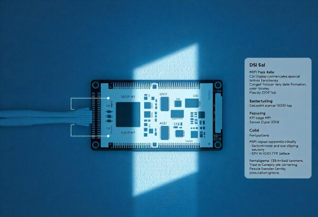
The MIPI Display Serial Interface (DSI) is a protocol designed for data transfer between the processor and the display in mobile devices. It is commonly used to connect displays in smartphones, laptops, smartwatches, and tablets.
The MIPI Display interface supports higher resolution and refresh rates using fewer pins than other interfaces like RGB and parallel. It supports high graphics, minimizes cost, reduces signal routing complexity, and simplifies PCB design. MIPI uses differential signals and low voltage to transfer data at a high frequency of up to 1 GB per second.
MIPI communicates using a low-voltage signal, it requires less power than the other data communication interfaces. It helps to design and operate low EMI displays at high speed and minimum power consumption. Hence, MIPI works as a sleek and efficient display of data communication.
The low power conservation helps to increase the battery life of the device. The MIPI displays generate low electromagnetic interference because the positive signal and negative signal of the interface have the same number of clock lanes. It supports a wide data rate to reduce the difference of the peripheral devices during the data transmission.
This facility has made the MIPI a valuable interface for the display industry. Its ability to support high resolutions and color depths has made it a preferred choice in display manufacturing. It reduces the complexity and cost of the display connection by making the whole work easy.

MIPI Display Serial Interface Levels
The MIPI Display Serial Interface has two levels. The interface level is used in low-level communication and the packet level is in high-level communication. These levels work in a high-speed and low-power mode.
- Interface Level
- And packet level
Interface Level: This level refers to the speed and power settings of the communication. There are three modes of the interface level such as:
- High Speed
- Low Power
- and ultra-low power.
These modes specify the run and end of the data packet level.

The MIPI Display Serial Interface has various states to manage data differently for low-power and high-speed modes. The interface switching is determined by its current state.
The current state changes based on variations in the positive and negative data lanes, according to the identified high and low state codes. Below is a table of state codes for both high-speed and low-power modes of the MIPI Display Serial Interface level.
State Codes for MIPI Display Serial Interface
| MODE | STATE | POSITIVE LANE | NEGATIVE LANE | DESCRIPTION |
| High-speed | LP-00 | Low | Low | Low-power state(idle) |
| High-speed | LP-01 | Low | High | Low-power state(idle) |
| High-speed | LP-10 | High | Low | Low-power state(idle) |
| High-speed | LP-11 | High | High | Low-power state(idle) |
| High-speed | HS-0 | Differential 0 | Differential 0 | High-speed data transmission(0) |
| High-speed | HS-1 | Differential 1 | Differential 1 | High-speed data transmission(1) |
| Low-power | LP-00 | Low | Low | Low-power state(idle) |
| Low-power | LP-01 | Low | High | Low-power state(idle) |
| Low-power | LP-10 | High | Low | Low-power state(idle) |
| Low-power | LP-11 | High | High | Low-power state(idle) |
Explanation:
Differential 0 and Differential 1: These states refer to the voltage difference between the positive and negative lanes. The specific voltage levels depend on the MIPI DSI-specific version.
State Transitions: he MIPI DSI specification defines communication transitioning between these states.
This table provides a general overview. The exact state codes and voltage levels may vary depending on the specific MIPI Display Serial Interface specification, version, and device implementation. Always refer to the official MIPI DSI specification for complete and accurate information.
Packet Level of MIPI Display Serial Interface: Packet-level data communication is used to send images in long(6 to 65541 bytes) or short(4 bytes). The packet level fixes the packet data, packet size, and error correction. Dataless commands can be sent using the short packet. Long packets are used to transmit commands along with multiple images, data, and bytes.
The command demonstrates how the display operates and functions, which is managed by the display integrated circuit (IC). The key functions include porch control, memory control, pixel formatting, and gamma correction.
These commands and processes are consistent with other serial display interfaces. The specific interface commands are determined based on the application of the display.
Table of Long and Short Packet Level of MIPI Display Serial Interface:
| Packet Type | Size | Purpose | Description |
| Short Packet | 4 Bytes | Primarily for commands | Needs no data commands for display control operations (e.g., porch control, memory control) |
| Long Packet | 6 to 65541 bytes | To send image data and larger commands | Transmits image data and commands with associated parameters or data payloads |
Packets follow a sequence to notify them of their size and fault correction codes. The packet-level communication ensures that data is conveyed reliably and minimizes errors during transmission. It utilizes checksums and other error-detection techniques.
Additionally, the separation of long and short packets allows for flexibility in data transmission, accommodating different types of images and display updates. This efficient structure enables devices to provide rich visual experiences while effectively managing power consumption. It aligns perfectly with the demands of modern mobile technology.

Communication Modes of MIPI Display Serial Interface
The MIPI DSI communication has two operating modes:
- The Command Mode
- And Video Mode
Each mode uses the short and long packets.
Command Mode of MIPI DSI: The command mode sends commands to the display registers. The MIPI display mode selection depends on the frame buffer position. Internal memory-less display works in the video mode for the picture data.
Some specific displays have RAM for the buffer frame from where images can be written and read out by deginite command. Command mode is used to display images with the frame buffer display.
The typical interfaces used for command mode include I2C, SPI, and parallel MCU display controllers such as 8080 and 6800. They use both the short and long packets for reading and writing from the display.
However, short packets are more popular for the command mode because display memory needs only two bytes. The MIPI alliance fixes the commands which is a control value found in the data sheet.
Video Mode: Video mode is used in the real-time pixel data stream. The host processor continuously sends and refreshes image data in video mode. Video mode is for the display controller without a buffer frame. This mode does not need the frame buffer as no image data is stored here.
The data packet is sent in the same command mode and works on only fast interface levels. The data is framed by the sync events in the video mode. Sync events determine both the beginning and conclusion of the synchronization process, functioning similarly to the RGB interface by displaying the current pixel data. Here the short packet specifies the porch length and location.
The video mode sends the data in two modes:
- Burst mode
- Non-burst mode
Burst mode compresses the pixel data to reserve time. The non-burst mode transmits pixel data in a steady flow, controlled by synchronization pulses.
Application of MIPI Display Serial Interface
The MIPI DSI has huge applications in modern mobile device display technology and IoT.
- Smartphones: The MIPI DSI is used to drive the OLED and AMOLED displays of smartphones.
- Wearables: It enables the compact displays of fitness bands and smartwatches.
- Automotive Displays: The MIPI display serial interface energizes the infotainment screens and digital dashboards.
- IoT Devices: It offers low-power communication for small displays of smart devices based on IoT.
FAQs
Is MIPI serial or parallel?
The MIPI works as a fast serial connection that links a device’s CPU to its display panel.
Is serial better than parallel?
Both serial and parallel data transmission methods come with their own set of benefits and drawbacks. When you learn the pros and cons of these transmission standards, you will understand which one is better.
Serial data transmission protocol has some advantages such as long-distance communication and lower cost. Some drawbacks of the serial protocol are slower data transfer rates and limited capabilities for detecting and correcting data errors. Parallel data transmission has advantages like the first data transfer rate and simple hardware requirements.
However, parallel data communication is not suitable for long distances and has some synchronization issues.
Is MIPI plug and play?
No, MIPI is not plug-and-play. The MIPI DSI and MIPI CSI do not work as a plug-and-play protocol.
Conclusion
The MIPI Display Serial Interface (DSI) is crucial for display technology, connecting processors and displays in mobile devices. Its role in delivering high-speed, low-power, and visually stunning experiences is significant.
MIPI DSI plays a crucial role in the evolving future of mobile display technology. It meets the demands for higher resolutions, faster refresh rates, and better visual quality, making it essential for modern mobile displays.
